
A carbide insert intended for a brazed steel assembly should be ordered with the joint design in view. Bonded faces, support, material pairing and the finishing sequence can affect whether an otherwise acceptable insert works in the completed assembly.
For custom carbide wear components, send the assembly context as well as the insert drawing. This guide concerns the information needed to specify the carbide part. It does not state that Extramet provides brazing or replace a qualified joining procedure.
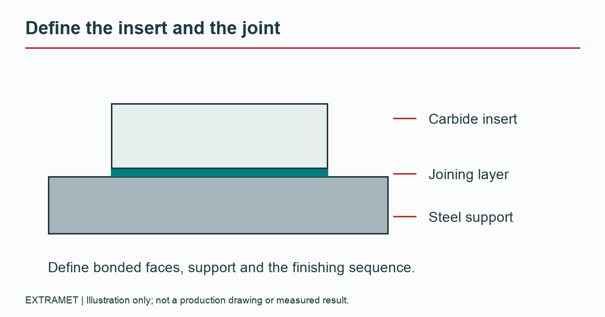
Identify the faces intended to be bonded
Mark the intended joining surfaces on the drawing. A joint along one face and a joint that constrains an insert on several faces are not the same design problem. The joining specialist needs to understand how the carbide is restrained as the assembly heats and cools.
Cemented carbide and steel generally expand by different amounts with temperature. Once bonded, that mismatch can contribute to stress. The actual response depends on both materials, the geometry, the joining layer and the temperature history; a single “carbide versus steel” expansion ratio is not an assembly design rule.
Separate insert and joint requirements
| Item to define | Responsibility to resolve |
|---|---|
| Carbide grade and geometry | Which insert drawing and material requirement govern supply? |
| Steel grade and condition | Who confirms compatibility with the intended joining cycle? |
| Bonded faces and joint space | Who approves the joint design and its dimensional requirements? |
| Surface preparation and condition | What is delivered by each supplier, and what is done before joining? |
| Final grinding and inspection | Which requirements apply before joining and which apply to the assembly? |
For example, a supplier may quote a rectangular carbide strip to its standalone drawing, while the assembly contractor expects a specific joint space after locating it in a steel pocket. If neither drawing explains how those requirements relate, both companies can follow their own print and still disagree at assembly.
Resolve that interface on the controlled drawings. Do not use a universal joint-gap number from an online article: the filler system, joining method, materials and approved procedure must determine the applicable requirement.
Review support and exposed edges
Explain how the finished component is loaded. Identify the working face, the direction of contact and the sections that remain unsupported. A carbide edge that carries load outside the supported region may require a different design discussion from a fully backed wear face.
The goal is to let the designer and joining specialist assess the whole load path. An insert drawing that omits the steel support, contact direction or corner details can hide the reason a previous assembly chipped or cracked. Failure photographs and the location of damage are useful context, not proof of a particular cause.
Agree on the condition at each handoff
State whether the carbide arrives as flat stock or a preform or with particular surfaces finished. Identify which machining occurs before joining and which dimensions are checked afterward. Do not assume a dimension measured on a loose insert guarantees the corresponding dimension in the completed assembly.
The near-net versus finish-ground guide helps divide those responsibilities. A clear handoff also identifies who handles surface preparation and confirms that the delivered surface condition is suitable for the joining process.
Download the fillable carbide insert joint-review worksheet (PDF).
Keep the process approval with the joining specialist
Filler choice, flux, atmosphere, heating, cooling and operator protection belong to a qualified procedure and current supplier safety information. They should not be improvised from a material-sourcing checklist. In particular, do not assume that a historical filler recommendation is suitable for a current workplace or product requirement.
Before ordering, obtain agreement on the insert print, assembly print, joining responsibility and acceptance evidence. Those four items turn an ambiguous request for a “brazable carbide piece” into a reviewable supply requirement.
Joint-design questions
Does this guide specify a brazing temperature or joint gap?
No. Those depend on the approved joining system and assembly. The responsible specialist must establish them.
Should the carbide supplier see the steel assembly drawing?
Yes, when the assembly affects the supplied insert’s geometry, surface condition or inspection requirements. Identify the responsibilities of each party.
Technical references
- Federal Carbide: brazed carbide component design considerations
- General Carbide: Designer's Guide to Tungsten Carbide
Questions about the supplied carbide part? Contact Michael Douglas, Extramet Products product expert, or send the drawing and requirements for review. Application-specific approval belongs with the responsible technical and quality reviewers.