
The clearance between a carbide pin and a steel bore can change with temperature because the two materials may expand by different amounts. Start with the actual pin and bore dimensions at a stated reference temperature, then use material-specific expansion data for the operating range.
When specifying precision carbide pins, include the mating component and temperature conditions. A room-temperature diameter alone may not describe the fit in service. The example here concerns an unbonded clearance fit, not a shrink-fit assembly or a brazed joint.
A first-order calculation
For a freely expanding feature over a range where a constant coefficient is a suitable approximation, dimensional change can be estimated as:
Change in diameter = reference diameter x linear expansion coefficient x temperature change.
Calculate the bore and pin separately. Diametral clearance is bore diameter minus pin diameter. The coefficients, temperatures and dimensions must use compatible units; a temperature difference of one degree Celsius has the same magnitude as one kelvin.
Worked example with assumed values
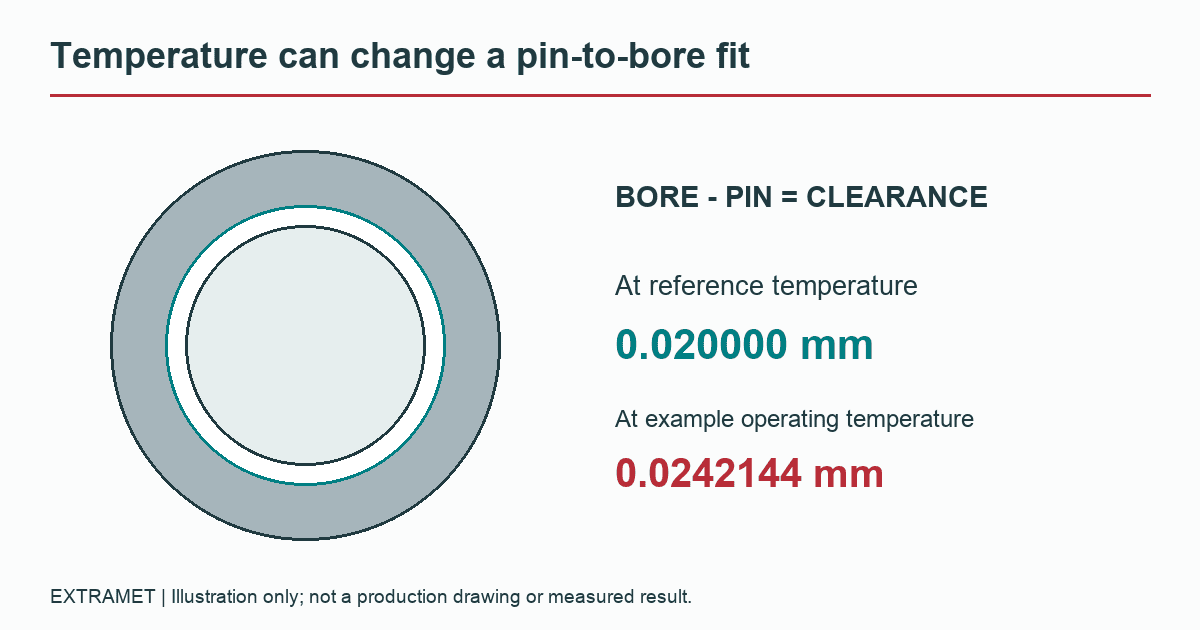
Assume a pin measures 10.000 mm and its bore measures 10.020 mm at 20 degrees Celsius. For this arithmetic example only, use 5 x 10⁻⁶/K for the pin and 12 x 10-6/K for the housing. Assume both reach 80 degrees Celsius uniformly and expand freely. These are illustrative coefficients, not certified data for a named Extramet grade or steel.
| Quantity | At 20 degrees Celsius | Change over 60 K | At 80 degrees Celsius |
|---|---|---|---|
| Pin diameter | 10.000 mm | 10.000 x 0.000005 x 60 = 0.003000 mm | 10.003000 mm |
| Bore diameter | 10.020 mm | 10.020 x 0.000012 x 60 = 0.0072144 mm | 10.0272144 mm |
| Diametral clearance | 0.020000 mm | Increase of 0.0042144 mm | 0.0242144 mm |
Under those assumptions, the clearance increases by about 4.21 micrometers. That is a diametral change; for a centered pin, the change in radial gap would be half as large. Keep the distinction clear when comparing the result with a drawing or assembly requirement.
Check the temperature difference between the parts
The same-temperature assumption matters. If only the illustrative pin reached 80 degrees Celsius while the bore remained at 20, the clearance would instead be 10.020 – 10.003 = 0.017 mm. This is not a prediction of a particular machine; it shows why separate pin and housing temperatures belong in the calculation.
A startup transient, local heat source or temperature gradient may invalidate a uniform-temperature model. Mechanical restraint can also change the response. Those cases require a more complete design analysis than the free-expansion arithmetic above.
Bring tolerances back into the calculation
A nominal clearance is not the worst-case clearance. At the reference condition, the smallest clearance comes from the smallest allowed bore and largest allowed pin. Evaluate the relevant dimensional limits and temperature cases together before deciding whether the fit remains acceptable.
The OD tolerance and inspection guide explains why diameter, form and measurement conditions need separate attention. Straightness, roundness, alignment, debris and lubrication can affect function even when a simple clearance calculation is positive.
Download the fillable pin-and-housing fit worksheet (PDF).
Use the actual materials and function
Obtain expansion data for the specified cemented-carbide grade and steel over the applicable range. Do not substitute pure-tungsten values for cemented carbide. Record the source and whether the coefficient is an average over a range or another stated basis.
Explain whether the pin locates, guides or forms a workpiece, as discussed in the carbide pin application guide. The responsible designer must establish acceptable operating clearance and evaluate load, wear and assembly conditions. This worksheet organizes the inputs; it does not authorize a fit or an assembly-heating procedure.
Temperature and fit questions
Does a steel bore always become looser around carbide when heated?
No universal answer applies. It depends on both materials, their temperature changes, restraint and the starting dimensions. Calculate the actual case.
Can this example be used to choose a press fit?
No. An interference fit requires its own stress, geometry, material and assembly analysis. The example assumes an unbonded clearance fit and free expansion.
Technical references
Questions about the supplied carbide part? Contact Michael Douglas, Extramet Products product expert, or send the drawing and requirements for review. Application-specific approval belongs with the responsible technical and quality reviewers.