
A carbide saw tip has a width before it becomes part of a finished blade. That supplied width, the blade’s specified kerf and the thickness of its steel plate describe different boundaries. Keeping them separate helps a saw maker order the right starting component and leave the intended material for finishing.
For carbide saw-tip requirements, begin with the component drawing and supplied condition. A finished-blade kerf dimension provides useful context, but it does not by itself define the loose tip to order.
Supplied tip width, finished kerf and plate thickness
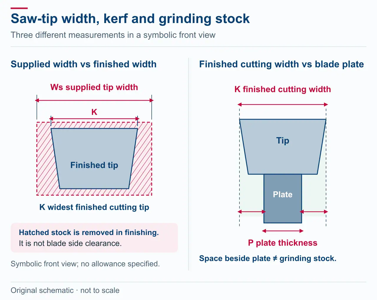
On a conventional carbide-tipped circular saw, the finished teeth project beyond the sides of the steel plate. Their cutting edges establish the blade’s nominal cutting width. Ridge Carbide Tool’s glossary defines kerf at the widest point of the carbide tip and describes the radial and tangential relief behind the cutting edge separately.
In the illustration, Ws is the supplied tip width, K is the nominal finished cutting width, and P is the plate thickness. The arrows compare these boundaries in a simplified front section. Confirm the actual view and dimension names on the supplier’s drawing; “width” is meaningful only when its direction is clear.
Grinding allowance is material that will be removed
If the tip will be side-ground after supply, its starting shape needs the stock required by that finishing process. In a simple section, the supplied width equals the finished width plus the stock on the left and right:
Ws = K + left-side stock + right-side stock.
When those stock amounts are equal, each is half the difference between supplied and finished width. This describes where the material is; it does not determine how much allowance a particular process needs. Starting-size variation, tooth geometry and the finishing sequence still have to be addressed on the drawings.
Some tips arrive with selected faces already finished. Others require further grinding. The near-net versus finish-ground guide explains how to separate the dimensions accepted at delivery from those accepted after downstream finishing.
Clearance remains after the grinding stock is gone
The finished tip also projects beyond the plate. In the same idealized, centered section, that projection on each side is (K − P) ÷ 2. This compares the finished tooth with the steel body. Grinding stock instead compares the supplied tip with its finished shape.
Consider a deliberately hypothetical example: a supplied width of 4.0 mm, a finished cutting width of 3.6 mm and a plate thickness of 2.6 mm. Equal side finishing would remove 0.2 mm from each side of the tip. The finished tooth would still project 0.5 mm beyond each side of the centered plate.
The 0.2 mm and 0.5 mm answer different questions. The first is stock removed; the second is the remaining geometric projection. These invented dimensions illustrate the arithmetic only. They are not recommended tip dimensions, allowances or blade-clearance limits.
The finished tooth is more than a rectangular outline
Actual teeth can have relief from top to bottom and from front to back. Their width therefore changes away from the widest cutting point. A section showing three nested widths does not define those relief angles or the complete tooth profile. Asymmetric teeth also require their actual left and right dimensions.
Hyperion’s circular saw-tip information identifies the saw plate, material selection, brazing and grinding quality, and tooth geometry as separate contributors to the finished blade. A correctly supplied tip is one part of that assembly.
Keep the nominal blade-width specification separate from acceptance of a measured cut, too. The loose-tip width alone cannot establish either the completed tooth profile or the cut produced by the assembled tool.
Make the dimensional handoff explicit
Identify the supplied envelope and finished tooth profile on the drawing, with the measurement locations and surfaces already finished at delivery. The blade maker can then confirm the stock needed for its process and the acceptance requirements for the completed assembly.
Send your saw-tip drawing for review. Extramet reviews the requested component, grade and supplied condition with its supply partner and confirms the available scope through the quotation.