
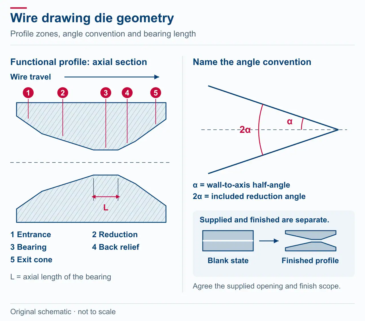
A wire drawing die guides incoming wire through a reduction zone and a sizing bearing before releasing it through the relief and exit. Each zone has a different function. The bore diameter alone cannot define the profile: angles, transitions and bearing length also describe how the wire meets the die.
For buyers of carbide wire drawing die nibs, the useful distinction is between the profile specified for the supplied nib and the finished working profile of the die. The illustration below identifies the geometry without prescribing an angle, reduction or production setting.
The entry brings wire and lubricant into the profile
The entrance, sometimes called the bell, opens toward the incoming wire. It provides access to the working profile and a path for drawing lubricant. Its transition into the reduction zone is a separate feature from the final sizing bore.
A smooth transition avoids treating the junction as an unintended sharp edge. This is one reason a simple hole diameter leaves important information out of a die drawing.
The reduction zone changes the wire section
The incoming wire first meets the working surface within the approach or reduction cone. As the wire is pulled through this converging region, its cross-section decreases and its length increases. The reduction zone therefore performs a different job from the opening that admits the wire.
Contact location depends on the relationship between the incoming wire and the profile. Moving from one incoming size to another while keeping the die drawing unchanged is not the same geometrical condition. Likewise, two dies with the same final bore can have different approach profiles. These relationships explain why an application drawing needs more than a single diameter, without implying a universal optimum angle.
Define the angle before comparing drawings
In this article’s diagram, α is the half-angle between one side of the reduction cone and the bore axis. The full included angle between the two sides is 2α. These labels describe the same cone from different reference lines.
A drawing that says only “reduction angle” can leave that convention unclear. Confirm whether the value refers to the included angle or the angle to the axis before comparing quotations or profiles. The symbols here are definitions, not recommended numerical settings.
The bearing is the straight sizing region
The bearing follows the reduction zone. This short, substantially parallel part of the bore defines the sizing region and affects the wire surface. Its axial length is labeled L in the diagram. L is neither the cone length nor the total height of the carbide nib.
Keeping those dimensions separate prevents a common drawing ambiguity: “length” may otherwise refer to the whole blank or to a functional internal feature. The intended bearing length belongs with the bore profile. It should not be reconstructed from the overall nib dimensions or copied from a different die material’s general guidance.
Relief and exit release the wire
Back relief is the transition after the bearing that lets the wire move away from the sizing surface without encountering an abrupt exit edge. The larger exit cone continues the opening toward the back of the die while leaving material around the working profile. It is not a second sizing bearing.
Viewed together, these zones create a clear sequence: admit the wire, reduce its section, size it, then release it. Use that sequence to read an axial section. It helps distinguish a missing feature from a feature drawn with an unfamiliar name.
Identify which profile the nib supplier must provide
A nib specification may describe outside diameter, axial height, bore features and supplied condition separately. The agreed drawing must identify what is supplied and what the die maker subsequently finishes; there is no universal unfinished zone or grinding allowance.
Keep the broader blank-versus-finished distinction in that handoff.
Buyer handoff checklist for carbide drawing-die nibs
Separate what the nib supplier provides from the final die profile that is completed later. This checklist covers the nib component, not a finished mounted die.
- Supplied nib: outside diameter, height, core opening and finishing allowance, as agreed on the drawing
- Final die profile: angle convention, stated as included angle or half-angle
- Bearing length, kept separate from nib height
- Wire alloy, incoming and outgoing wire sizes
- Quantity
Agree in writing who completes each finishing step before quoting.
For a carbide nib inquiry, share the profile drawing when available, the wire material and the condition in which you need the component supplied.